Hot search: 3KW electromag
Aluminum forgi
1T one belt tw
15KW electroma

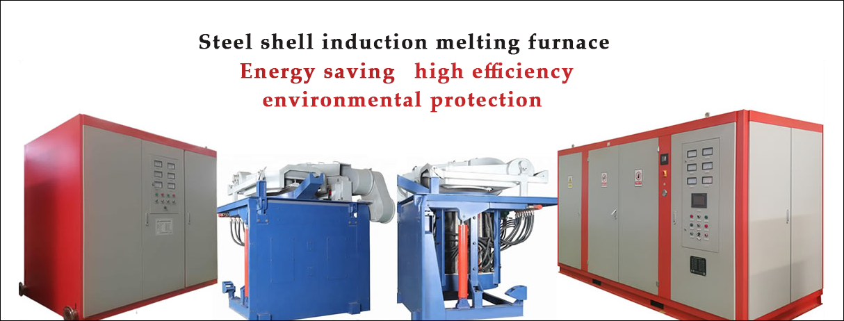
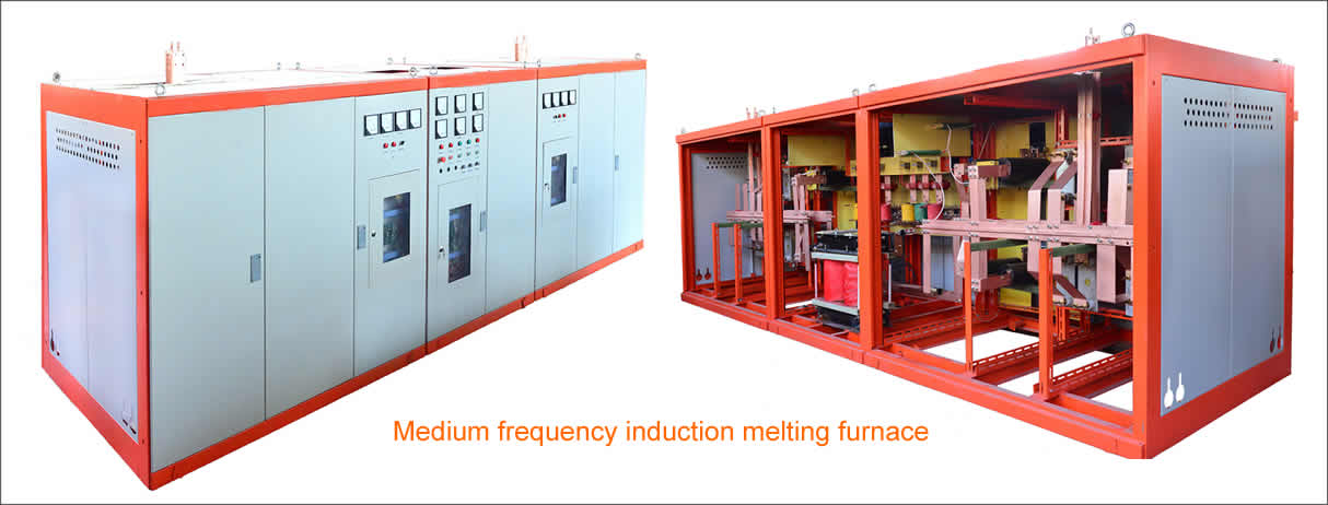
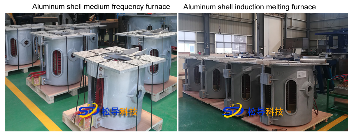
2T induction melting furnace technical performance standards
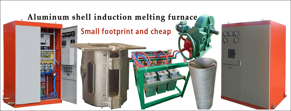
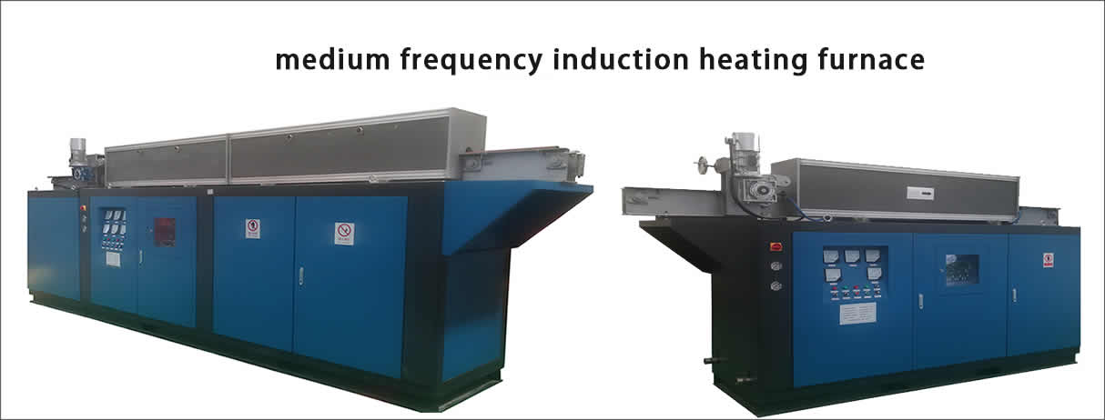
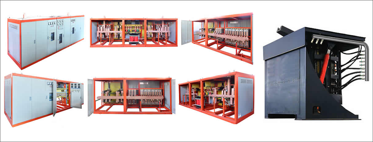
A, medium frequency induction melting furnace power supply selection of 2T
1. The power supply is a fully digital control circuit, which adopts large-scale integrated chip control to ensure stable and reliable power supply operation and low failure rate.
2. The intermediate frequency power supply adopts adaptive automatic adjustment mode in the whole process of heating and melting, and always maintains the timely maximum power output.
3. The power protection function is perfect, and the protection measures include:
3.1 Main circuit short circuit protection.
3.2 Main circuit phase loss protection.
3.3 Cooling water temperature protection.
3.4 Cooling water underpressure protection.
3.5 IF over voltage protection, over current protection, overload protection, control power supply under voltage protection.
3.6 Inverter thyristor current rise rate high protection (commutation inductance).
3.7 Rectifier side fast fuse protection.
3.8 Excellent impact load resistance.
4. The output power should be able to be smoothly and continuously adjusted under the rated load impedance. The adjustment range is 10%-100% of the rated power. And can adapt to the process requirements of the furnace lining oven.
5. The output voltage and current can be automatically kept within the limit value (or rated value) during the continuous change of the load.
6, with strong starting performance and load adaptability, can be started frequently under light and heavy load, the startup success rate is 100%.
7. The impedance regulator automatically adapts to load changes, so that the equipment parameters are always running at the optimum state.
8. The output frequency should be automatically followed when the load impedance changes. The range of variation is -30% of the rated value---+10%. When the rated power is output under rated load, the frequency variation range does not exceed ±10%.
9. The main board has a current balance automatic adjustment tracking device.
10. The cabinet design conforms to national standards.
11, connecting copper row load flow: power frequency 3A/mm2; intermediate frequency 2.5A/mm2; tank road 8-10A/mm2;
12. In the case of no water, the insulation resistance and insulation withstand voltage test are in line with national standards.
13. Temperature rise: After the device is continuously operated at rated power until the temperature rises, the copper bars and electrical components meet the respective standards.
B, 2T induction melting furnace flexible water-cooled cable:
The joints of the water-cooled cable are made of high-quality T2 material and crimped with copper strands by cold press forming process without strand breakage. The layout of the cooling water channel is reasonable, and single water cooling is adopted to ensure that the wire is sufficiently cooled. All fasteners are made of stainless steel to reduce eddy current loss, prevent heat generation and reduce failure. The jacket of the water-cooled cable is made of a special flame-retardant rubber tube and is subjected to a pressure of 0.45 MPa.
C, 2T induction melting furnace compensation capacitor bank:
The compensation capacitor cabinet is made of channel steel and angle steel, and is equipped with a safety net to make the overall structure firm and beautiful, and to ensure the insulation strength between the capacitor and the cabinet. The copper busbars of the capacitor bank are all made of large-section copper busbars and water-cooled systems to reduce the transmission loss of the parallel resonant circuit. The capacitor is connected to the main busbar by a copper busbar.
D, large-capacity DC filter reactor
Make sure that the filter core is not magnetically saturated with sufficient inductance.
The silicon steel sheet of the filter reactor is made of high-quality new cold-rolled high-conductivity silicon steel sheet, the copper tube is T2 extruded copper tube, and is wrapped with high-strength mica tape, and H-class insulation. Reduce the operating noise of the filter reactor. Copper tube size: 14*12*2
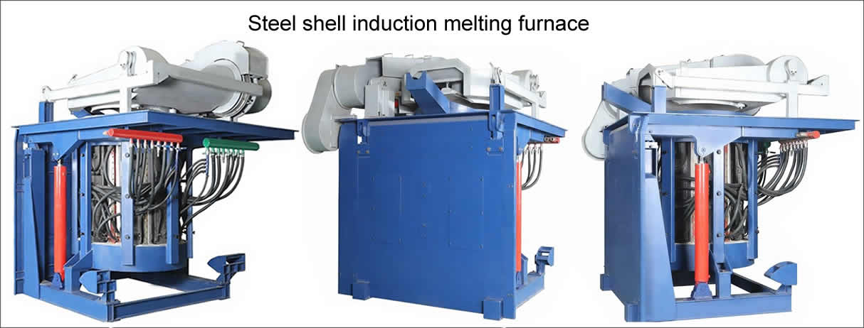
E , furnace body
The furnace body needs to be well matched with the intermediate frequency power supply to ensure the rated power output under rated capacity.
. 1, 2T induction melting furnace induction coil structure
Material:
The induction coil adopts T2 rectangular electrolytic cold-rolled copper tube with purity of 99.9%. The metal flow direction is uniform, the structure is dense with minimum copper loss and the highest electromagnetic conversion efficiency. The induction coil should take into account the influence of the inherent length of the copper pipe in the design of the waterway and the group. The welding part of the copper pipe is combined with the electric and water guiding parts, so that each group of induction coils is wound by the whole copper pipe. Weld seam.
The rectangular copper tube of the induction coil has a wall thickness δ ≥ 5 mm.
Winding process:
The induction coil is wound with a 50*30*5 copper tube.
The outer insulation of the induction coil is wound with mica tape and glass cloth tape, and the immersion process is twice wrapped twice. The withstand voltage of the insulation layer is greater than 5000V.
The induction coil is fixed by a series of bolts and insulating support bars welded to the outer circumference. After the coil is fixed, the pitch error of the coil should be no more than 2mm. All the bolts are in the form of a countersunk head in the insulating support strip to improve the insulation strength.
A stainless steel (non-magnetically permeable) water collecting cooling ring is arranged on the upper part and the lower part of the induction coil, so that the lining material gradually forms a gradient when the axial heat is received, and the service life of the lining is prolonged.
A copper tube magnetic collecting ring is disposed at an upper portion and a lower portion of the induction coil.
After the induction coil is completed, it needs to pass the 1.5 times maximum pressure water pressure compression test for 20 minutes to ensure that the induction coil has no water seepage.
The induction coil incoming line is the side entry line.
The inductor coil is made of copper tube of the upper copper tube factory, the size is 50*30*5, the number of turns is 18匝, the gap is 10mm, and the coil height is 1130mm.
2, 2T induction melting furnace of the oven rack mechanism
The hob is divided into two parts: the movable hob and the fixed hob.
The hob is required to be produced by the manufacturer, and the new steel and furnace structure are: reel type.
The movable hob is used to mount the induction coil and the yoke. The whole body of the furnace is welded by steel and steel plates. The operating platform at the top of the movable furnace frame is made of thick steel plate. The thickness of the steel plate is ≥8mm, and the thickness of the rolled steel plate is ≥16mm to improve the strength and load-bearing capacity of the hob.
The fixed hob is installed on the foundation, connected with the movable hob, and has a copper hinge and a lubricating oil nozzle. Under the pushing of the tilting cylinder, the movable hob can be tilted forward by 95 degrees.
The hob section is designed with a certain safety factor. Ensure that the hob has sufficient rigidity to run smoothly when carrying the maximum load.
The main cooling water separator of the furnace body is made of stainless steel pipe, and copper valve is installed in each inlet and outlet pipe (valve brand: Amyco).
The hob is welded by steel plate and section steel, which conforms to the general technical conditions of JB/T5000.3-1998 welded parts, and the welding is firm and flat. The column of the hob is made of 20# channel steel and 10mm thick plate. The bottom frame is made of 16# channel steel and 20mm thick steel plate.
. 3 2T induction melting furnace of the yoke structure
The yoke is made of high magnetic permeability cold-rolled silicon steel sheet, and the structure is water-cooled stainless steel splint type, and the thickness of the silicon steel sheet is 0.3 mm. The yoke adopts a contoured structure, so that the yoke can be closely attached to the outside of the induction coil, and the magnetic field of the coil is dissipated to the maximum extent, and the magnetic resistance of the external magnetic circuit is reduced. The insulation of the yoke and the induction coil is made of PTFE and asbestos rubber. The board material is insulated.
Material:
WISCO produces a new orientation of steel sheet, model 30Q130; the same batch of products.
Craftsmanship:
The yoke (to the induction coil) covers an area of 77.5% or more.
Total magnetic permeability area: ≥1600cm2.
The yoke is sandwiched between stainless steel plates and stainless steel on both sides, and is welded and fixed to improve utilization.
After the yoke is assembled, the bending degree is not more than 4 mm. Brushed and varnish protected after stacking.
The yoke water cooling is cooled by stainless steel water bags to ensure smooth water flow.
4, the furnace cover
The movable furnace cover adopts a manual mechanism, and the refractory material is knotted in the furnace cover.
5, furnace lining
The intermediate frequency coreless furnace lining shall conform to the thickness design size, and the baking and sintering process of the furnace lining shall be specified in the product specification, and the first furnace lining material of the two furnace bodies shall be provided by the supplier.
6. Apply refractory mortar layer to the inside and inside of the induction coil.
7, temperature rise
The surface temperature rise of each part of the intermediate frequency coreless furnace shall comply with the following regulations.
Part | Allow surface temperature rise (K) |
Stove, furnace shell, yoke | 75 |
Furnace floor, furnace cover | 200 |
Hydraulic system fuel tank | 35 |
8. Furnace lining detection device
The furnace lining detection device has the function of leaking furnace alarm and grounding detection, which can monitor the operation of the furnace body at any time. Once the detected data is abnormal, the system can issue an alarm and cut off the power supply to stop the main system work, so the leakage phenomenon can be eliminated. Production safety.
F , tilting hydraulic system
The main components of the tilting hydraulic system are hydraulic station, hydraulic operating table, tilting cylinder, oil pipe and so on. The furnace body can be turned over 95 degrees by pushing the cylinder, pour out all the molten steel, and can stay at any position during the turning process as needed.
The hydraulic station is composed of hydraulic valves, hydraulic pumps, explosion-proof valves and other valves and pressure gauges. The connection adopts advanced and reliable integrated block structure. The tilting operation is controlled by manual valve, which is convenient and reliable.
The hydraulic pump station is used to power the tilting cylinder, and the hydraulic medium is hydraulic oil.
The tilting table is used to control the tilting and falling of the furnace body. All hydraulic components are made of domestic famous products.
A conventional pump station start and stop and tilting furnace operating device are arranged on the integrated operation platform.
Copyright© 2007-2013 NO.6 Electric Mall All Rights Reserved