Hot search: 3KW electromag
Aluminum forgi
1T one belt tw
15KW electroma

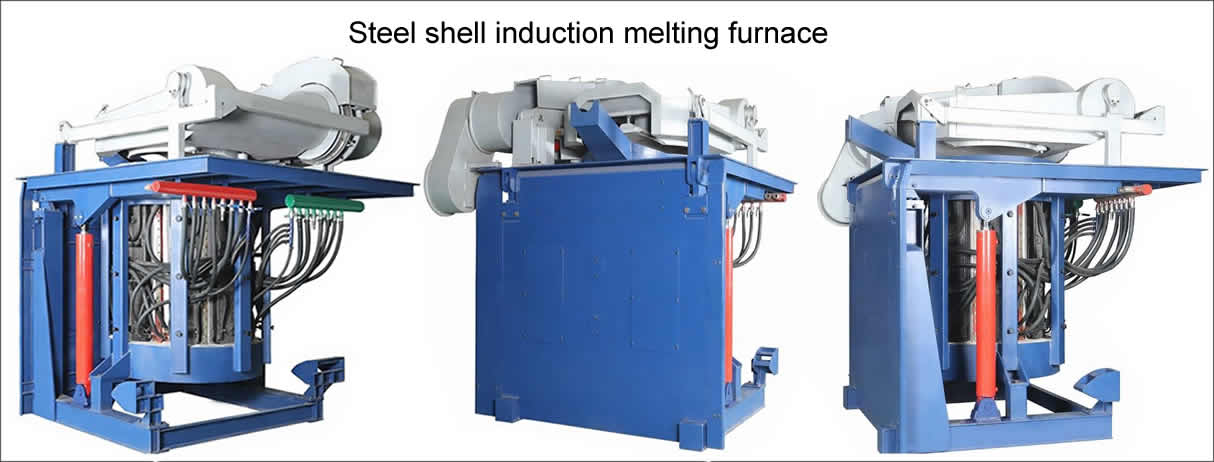
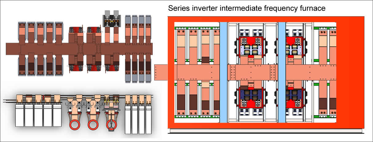
Induction melting furnace inverter part debugging method
1, closing the cabinet work inverter power source, power supply checking (multimeter)
+15 V, -15 V, +24 V , +30 V, + 130V whether to comply with requirements.
Check that each phase of the inverter cabinet through a ground line GND.
Check whether the inverter power pulse transformer work normally.
Check the inverter stop light (red) is bright, by working the inverter, inverter operating light (green) is bright, press the reset, inverter operating light (green) is off, the inverter stop light (red) is bright . By inverter work, green light,according to the inverter stop, red light. Repeat the operation more than a few times.
The green and red lights are off , and if the button is not working, check the load distribution board for any problems and the connection to the inverter board.
2, the shift switch is checked in the motherboard inverter, the inverter according to the working frequency table shows the frequency. KK tube oscilloscope trigger pulse is detected. ( with oscilloscope DC file )

Upon detection of pulses per one pulse inverter should check the negative bias, is: See oscilloscope to beat after pulse level to GN D, below 0.3V pulse voltage below GND

If no negative bias, check 380V / 10 V, 10 V, 10 V, 10V power transformer.
3, the correction frequency ( frequency table display and inspection frequency are consistent )
Check the frequency potentiometer W11 0, and adjust the frequency at 300HZ ( detected with an oscilloscope )
Correction frequency potentiometer W20 1, adjust potentiometer to make the frequency meter display 300HZ
4, test machine: (required: an inverter main board hit the working speed furnace crucible is placed, inside and outside the open water system.)
Closing the switch knife, according to energy storage, closing the shutter, press the button rectifying work.
DC voltage rises to full voltage ( DC voltage = incoming voltage × 1.35 × 2)
Detecting a current waveform on the inverter current transformer 5A / 0.1A probe with an oscilloscope.


The oscilloscope detected the waveform as follows


Adjust the power potentiometer , the current waveform changes as follows

The power regulator potentiometer, the current waveform can not be moved, the inverter main circuit current to the two signal lines are interchanged.
After the input current signal line is correct , adjust the power potentiometer to the zero position, and adjust the lower limit potentiometer W162 in the critical state (the second waveform above ).
Copyright© 2007-2013 NO.6 Electric Mall All Rights Reserved