Hot search: 3KW electromag
Aluminum forgi
1T one belt tw
15KW electroma

How to select SCR frequency furnace system elements correctly
Proper selection of power electronic devices such as thyristors and rectifiers is of great significance to ensure the reliability of the whole equipment and reduce the equipment cost. The selection of components should take into account factors such as the environment in which they are used, the cooling method, the type of the line, the nature of the load, etc., and take into account the economics under the condition that the parameters of the selected components have margins.
Since the application fields of power electronic devices are very wide and the specific application forms are various, the following only describes the selection of the thyristor components in the rectifier circuit and the single-frequency intermediate frequency inverter circuit.
1 rectifier circuit device selection
Power frequency rectification is one of the most commonly used areas for thyristor components. Component selection mainly considers its rated voltage and rated current.
(1) Positive and negative peak voltages VDRM and VRRM of thyristor devices :
It should be 2-3 times the maximum peak voltage UM of the component , ie VDRM/RRM=(2-3)UM . The UM values corresponding to various rectification lines are shown in Table 1 .
(2) Rated on-state current IT (AV) of thyristor device :
The IT (AV) value of the thyristor refers to the power frequency sine half-wave average, which corresponds to the effective ITRMS=1.57IT(AV) . In order for the component to not be damaged by overheating during operation, the actual rms value of the flow through component should be equal to 1.57IT(AV) after multiplying the safety factor by 1.5-2 . Assuming that the average load current of the rectifier circuit is Id and the current RMS value flowing through each device is KId , the rated on-state current of the selected device should be :
IT(AV)=(1.5-2)KId/1.57=Kfd*Id
Kfd is the coefficient of calculation. For the control angle α= 0O , the Kfd values under various rectifier circuits are shown in Table 1 .
Table 1: Maximum peak voltage UM of rectifier device and on-state average current calculation coefficient Kfd
Rectifier circuit | Single phase half wave | Single double half wave | Single bridge | Three-phase half-wave | Three-phase bridge | With balanced reactor Double anti-star | |
UM | U2 | U2 | U2 | U2 | U2 | U2 | |
Inductive load | 0.45 | 0.45 | 0.45 | 0.368 | 0.368 | 0.184 |
Note : U2 is the rms value of the secondary phase voltage of the main circuit transformer ; the single- phase half-wave inductor load circuit has a freewheeling diode.
Selecting the component IT (AV) value should also consider the component cooling method. Under normal circumstances, the rated current of the same component is lower than that of the water-cooled component ; in the case of natural cooling, the rated current of the component is reduced to one-third of the standard cooling condition.
2 IF inverter components selection
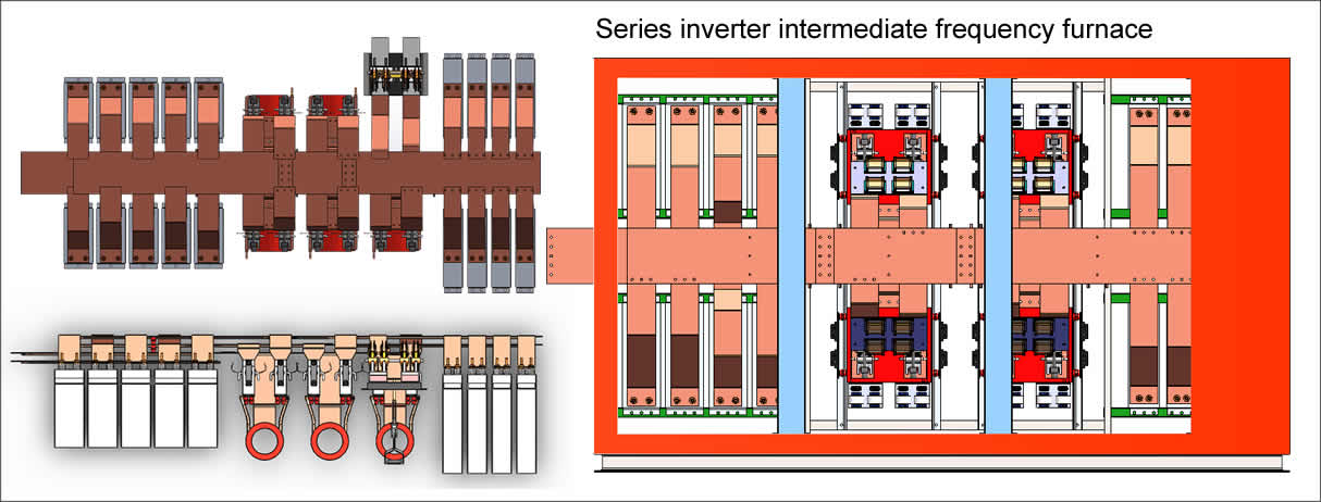
Under normal operating conditions 400HZ above, consider the use of the device KK; at frequencies above 4KHz, consider using the device KA. Here we mainly introduce the selection of components in the parallel inverter circuit ( see Figure 1 ) .

(1) The forward and reverse peak voltages of the components VDRM , VRRM components, forward and reverse peak voltages should be 1.5-2 times the actual maximum and reverse peak voltages . Suppose the inverter DC input voltage Ud, the power factor is cosψ:
VDRM/RRM=(1.5-2)πUd/(2cosψ)
Rated on-state current IT (2) element (AV) Considering the element work at higher frequencies, switching loss is significant, it should be rated on-state current flowing through the element 2-3 times its actual value I of To consider, ie
IT(AV)=(2-3)I/1.57
Assuming the inverter DC input current is Id , the selected device IT(AV) is
IT(AV)=(2-3)×Id/(1.57 )
(3) Shutdown time tq In the parallel inverter circuit, the off time selection of the KK component is determined according to the pre- initiation time tf and the commutation time tr . Generally take :
Tq=(tf-tr)×
(Tf when the power factor is about one cycle is 0.8, tr press element di / dt is less than or equal to 100A / μS determined) at higher frequencies can be by reducing the commutation time tr and the proper sacrifice A method of increasing the power factor by tf to select a componenthaving a suitable tq value
Copyright© 2007-2013 NO.6 Electric Mall All Rights Reserved