Hot search: 3KW electromag
Aluminum forgi
1T one belt tw
15KW electroma

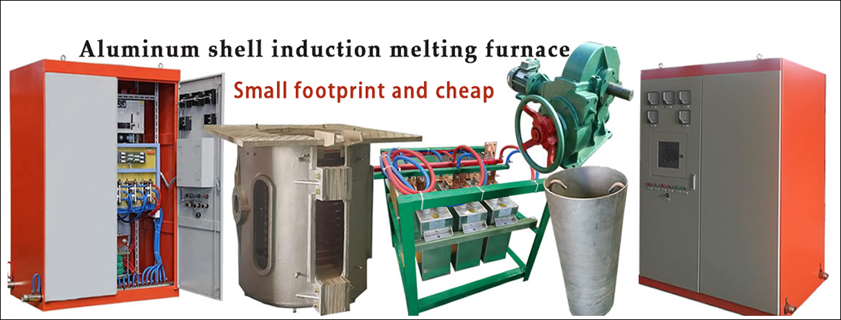
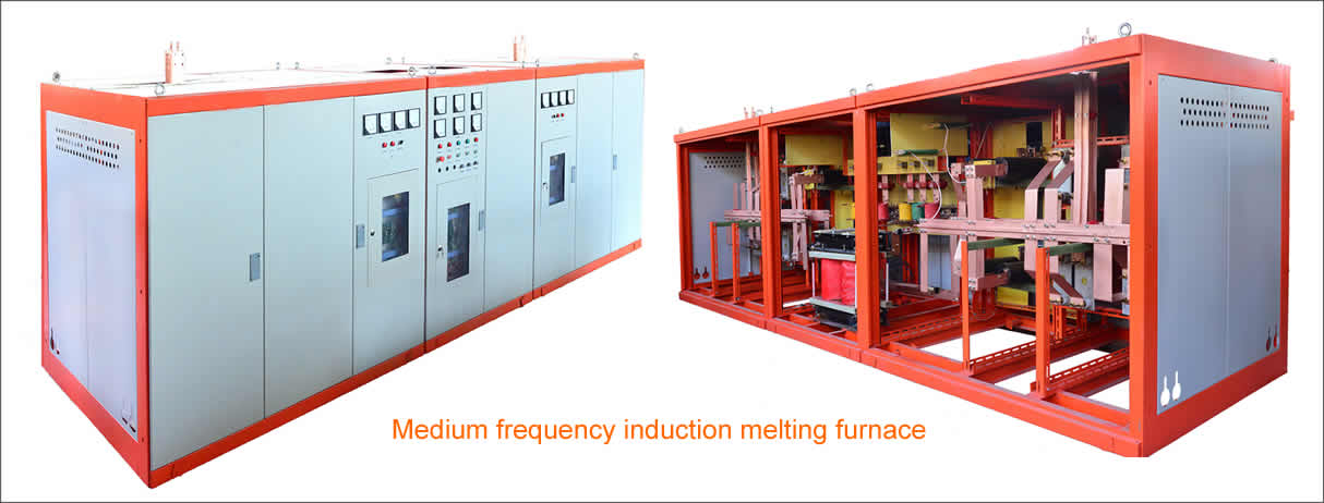
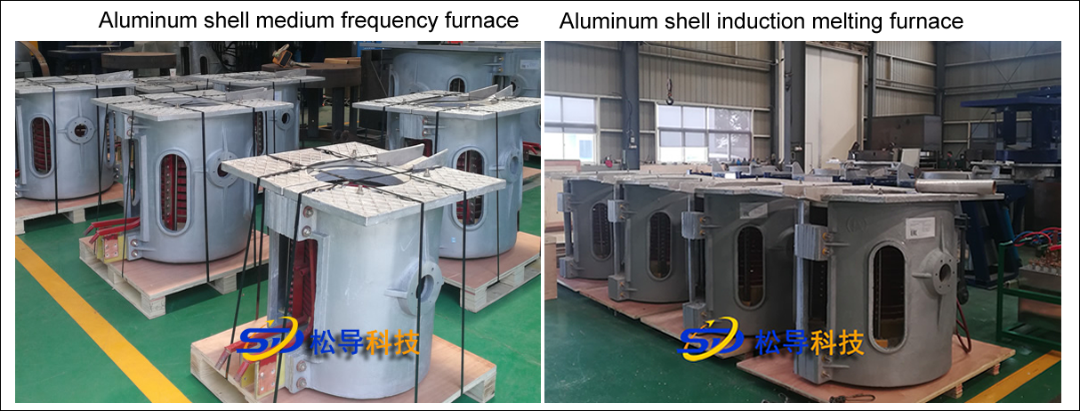
Method for selecting steel shell medium-frequency furnace steel shell body
1 , the furnace body
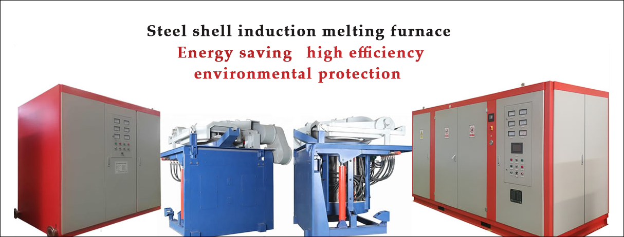
The furnace body is composed of an induction coil, a yoke, a hob, a tilting cylinder and the like.
Induction coil
The induction coil is made of 99.9% rectangular copper tube, and the induction coil is made of bandaged mica tape and immersion varnish . The exterior is then sprayed with a layer of gray insulating varnish, and the insulation layer has a withstand voltage greater than5000V .
The induction coil is fixed by a series of bolts and insulating stays welded to its outer circumference. After the coil is fixed, the pitch error is not more than 2mm .
 A stainless steel water cooling ring is arranged on the upper part and the lower part of the induction coil, and the purpose is to make the lining material uniformly heated in the axial direction and prolong the service life of the lining.
At the water outlet of the induction coil, several water temperature probes are installed according to the water path. When the water temperature of a certain road is blocked, the alarm can be immediately issued, and the intermediate frequency power supply can be automatically stopped.
1.2 , yoke
 The yoke is made of a high permeability cold rolled silicon steel sheet. The thickness of the silicon steel sheet is 0 . 3mm . The yoke adopts a profiling structure, and the arc of the inner arc surface is the same as the outer arc of the induction coil, so that the yoke can be evenly distributed on the outer side of the induction coil, thereby maximally restraining the magnetic field radiated outward from the coil and reducing the external magnetic circuit. Magnetoresistance.
The consumable yoke is clamped by stainless steel plates and stainless steel clamps on both sides and fixed by welding. A cooling water pipe is welded to the stainless steel plate on both sides for cooling the yoke. The cooling water pipe can withstand 0.45Mpa water pressure and no leakage within 15min .
After the yoke is assembled, the bending degree is not more than 4 mm , and the deviation between the theoretical center line and the actual center line is not more than 3 mm .
A PTFE sheet and an asbestos rubber sheet are interposed between the yoke and the coil. The PTFE sheet has high dielectric strength and high temperature resistance, and the asbestos rubber sheet has high heat resistance. This ensures insulation and heat resistance between the yoke and the coil.
Each yoke is fixed by a screw rod fixed on the furnace shell, and a uniform top force is formed in one circumference of the coil, so that the yoke is fixed and the coil is fixed, and the coil is not generated during the melting and discharging process. mobile.
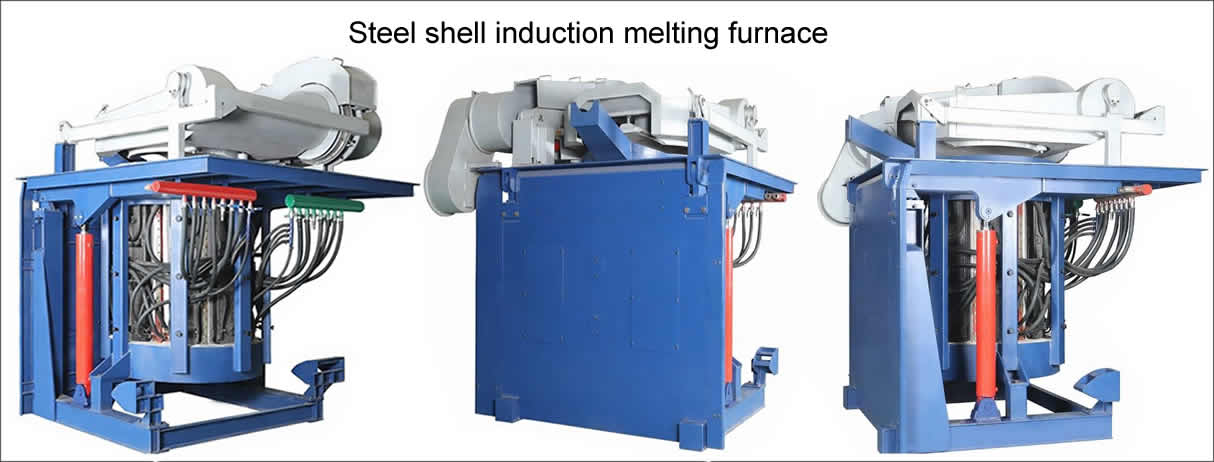
1.3 , hob
The hob is divided into two parts.
1.3.1 , movable hob
The movable hob is used to mount the induction coil and the yoke. It is welded from profiled steel and steel plate and has a frame structure for easy maintenance. The operating platform at the top of the movable hob is made of thick steel plate to improve the strength and load-bearing capacity of the hob.
1.3.2 , fixed hob
The fixed hob is mounted on the foundation for carrying the movable hob. The upper part of the fixed hob is connected by the tilting shaft and the movable hob. Under the pushing of the tilting cylinder, the movable hob can be tilted forward by 95 degrees.
The hob section is designed with a large safety factor. Ensure that the hob has sufficient rigidity to run smoothly when carrying the maximum load.
1.4 , furnace cover
A furnace cover is mounted on the movable hob. The operation of the furnace cover is either manual or hydraulic.
1.4.1 , manual furnace cover
The manual furnace cover is mounted on the rotating shaft on the side of the upper end of the furnace body, and the furnace cover can be opened and closed by pulling up and down the handle. When the furnace cover is added or not required, the furnace cover can be rotated to the side position of the upper part of the furnace body.
1.4.2 , hydraulic drive cover:
The hydraulically driven furnace cover is mounted on the rotating shaft on the side of the upper end of the furnace body, and the opening and rotating action of the furnace cover is realized by the action of the upper and lower oil cylinders and the rotating oil cylinder. Operate through the operation switch on the console. When the furnace cover is added or not required, the furnace cover can be rotated to the side position of the upper part of the furnace body.
Copyright© 2007-2013 NO.6 Electric Mall All Rights Reserved