Hot search: 3KW electromag
Aluminum forgi
1T one belt tw
15KW electroma


 Steel plate quenching and tempering production line
 drill pipe quenching and tempering line
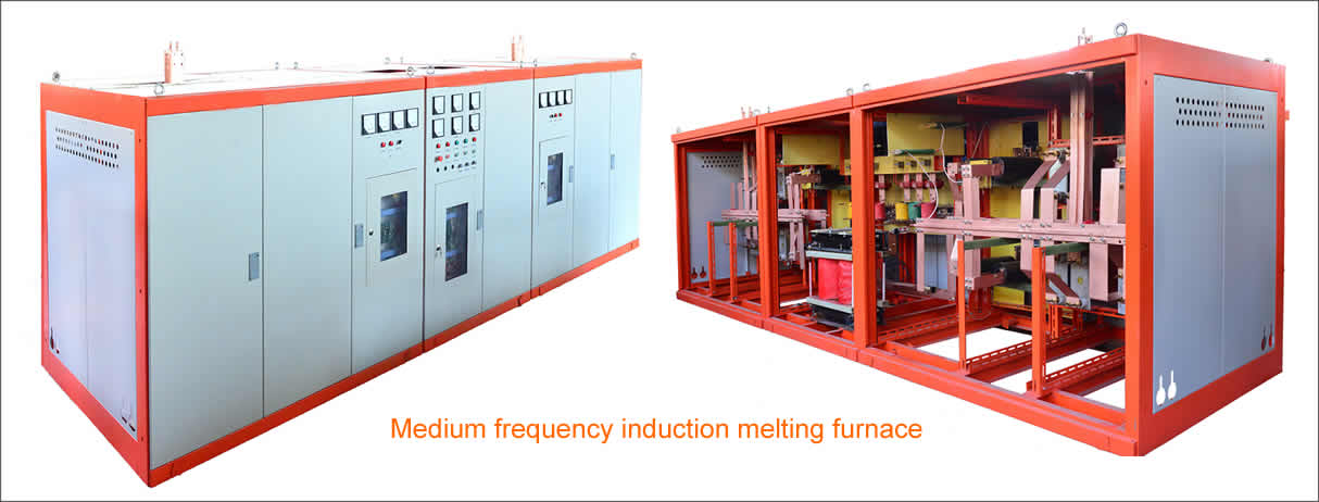
 Medium frequency quenching and tempering production line
 Tubing hardening and tempering line
 Petroleum oil drill pipe quenching and tempering line
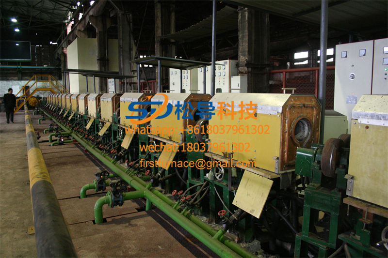 Pipe hardening and tempering
 Grinding rod quenching and tempering
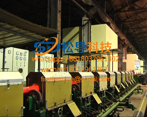 Drill pipe quenching and tempering
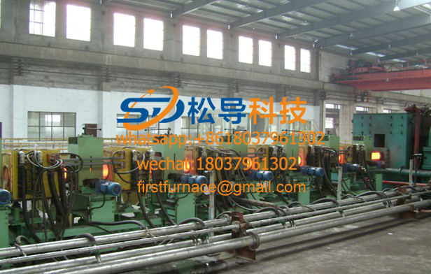 Φ219-1067 thick-walled steel pipe medium frequency inductio
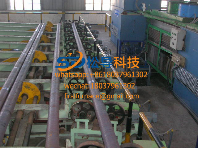 Φ219-1067 thick wall steel pipe medium frequency induction qSteel pipe spray quenching production line
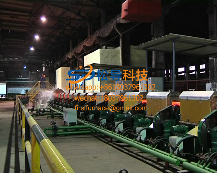 steel pipe quenching and tempering production line
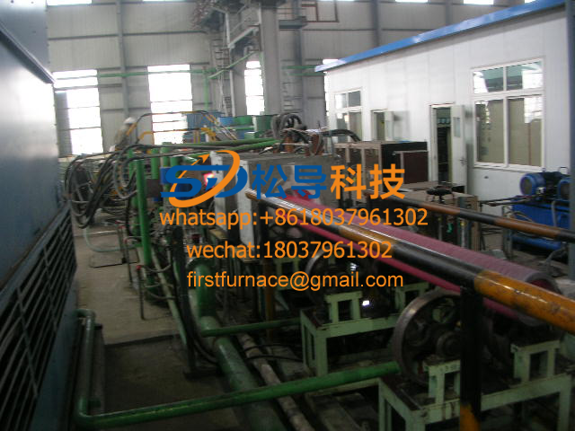 Steel grating induction heating system
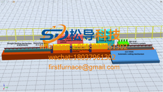 Steel rod quenching and tempering production line
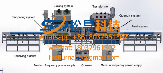 Single hydraulic prop quenching tempering
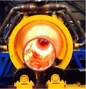 2700KW large diameter steel tube quenching and tempering prod
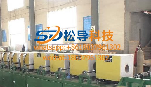 Quenching and tempering furnaces
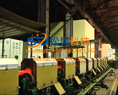 Sucker rod quenching and tempering production line
 Rebar quenching and tempering production line
Steel pipe spray quenching production line
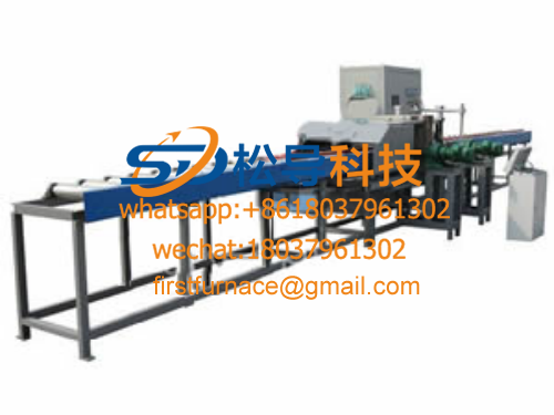
Fully automatic φ 219mm~ φ 533.4mm steel pipe spray quenching production line, the technical process of the production line and the technical characteristics of the equipment.
1. Main technical parameters of the production line
(1) outer diameter of steel pipe: φ 219mm~ φ 533.4mm, wall thickness: 7.35mm~57.17mm, length 6.0m~15m;
(2) The maximum weight of a single steel pipe: 4500 kg;
(3) Product steel number: N80, L80, P110
(4) Installed power: 2500kw
(5) Maximum productivity: 100 / hour
(6) Production: 220,000 tons / year
2 , Steel pipe spray quenching production line process selection method
The steel pipe is heated to about 1000 ° C by an induction heating quenching furnace and then sent to the material to be fed by the feeding roller. The feeding device holds the light pipe to the supporting wheel of the rotating device rotating slowly. The pressing device mounted on the outer shower frame quickly presses the steel pipe, and then the rotating device drives the steel pipe to rotate rapidly. The outer shower device is lifted up, and the outer shower pipe located directly above the steel pipe sprays water evenly on the outer surface of the steel pipe. At the same time, the internal spray device installed at the end of the steel pipe sprays water onto the inner wall of the steel pipe . The inner spray water flows through the entire steel pipe, is sprayed from one end, and is ejected from the other end. In this way, the inner and outer surfaces of the steel pipe are uniformly quenched during rapid rotation. After the quenching is finished, the pressing device is lifted up and the steel pipe is loosened. At the same time, the outer watering device retains the water gate, and the outer shower water is introduced into the water guiding tank, and is circulated back to the water pool through the pipeline. The steel pipe is sent to the stepping conveyor receiving position through the turning hook and the inclined frame. The stepper transporter transports the steel pipe to the empty water station after two working cycles. The air water device lifts one end of the steel pipe, and the compressed air blows off residual moisture in the steel pipe. The stepper transporter transports the steel pipe to the discharge roller, completes the quenching process, and the discharge roller feeds the steel pipe into the tempering furnace.
3 steel pipe spray quenching production line equipment structure and selection
3.1 Feed roller
The feed roller path is composed of a plurality of roller rollers, a positioning baffle and a detecting and detecting device. The spacing between the rollers is 1.8m. Each roller is mainly composed of a V-shaped roller, a motor reducer, two bearing housings and a bracket. The center line of the V-shaped roll is at an angle of 84 degrees to the axis of the steel pipe. As shown in Figure 1. The rotation of the roller drives the steel pipe to advance axially, and the radial friction force causes the steel pipe to rotate, so that the red hot steel pipe side is downward, and the bending deformation is caused by its own weight.The V-shaped rolls of the same speed have different feeding speeds for different diameter steel pipes, the diameter of the steel pipes is large, the feeding speed is fast, the diameter of the steel pipes is small, and the feeding speed is slow. The reducer adopts frequency conversion speed regulation, so that the steel pipes of different diameters can reach a reasonable feeding speed. A detection device is arranged in front of the positioning baffle. When the steel pipe approaches the positioning plate, the detecting device sends a message, the roller speed decreases, the steel pipe decelerates and slowly approaches the positioning baffle to prevent the severe impact from damaging the steel pipe section.
3.2 feeding device
The function of the loading device is to support the red hot steel pipe from the feed roller to the support wheel of the rotating device. The device is designed by the Swinton lever principle, and is mainly composed of a main shaft of the motor reducer (not shown) and a plurality of swing arms with a pitch of 1.8 m. The number of swing arms depends on the length of the steel pipe. Each swing arm consists of a V-shaped block. The shaft, the fixed sprocket of equal diameter and the movable sprocket, chain and tie rod are composed as shown in Fig. 2. The V-shaped block and the movable sprocket are fixed to the rotating shaft by a key connection, and are hinged to the swing arm. The swing arm is fixed to the main shaft by a key connection. The fixed sprocket has a built-in bearing bush and a sliding fit with the main drive shaft, and is fixed on the support by the pull rod. The fixed sprocket and the movable sprocket are connected by a chain. When the loading device is working, the motor reducer drives the spindle swing arm to rotate. Assuming that the angular velocity is ω, the pulling speed of the V-shaped block with the swing arm is ω, the pull rod connects the fixed sprocket to the frame, and the speed of the fixed sprocket relative to the swing arm is (-ω), the movable sprocket and the fixed The sprocket and other diameters are equal to the angular velocity of the swing arm, and the angular velocities of the movable sprocket and the V-shaped block relative to the swing arm are (-ω). Thus, the algebraic sum of the synthetic proud speed of the V-shaped block is zero, and only the translation is not rotated. So no matter the angle of the swing arm is turned to any angle, the opening of the V-shaped block is always facing upwards to ensure that the steel pipe does not slip. A block brake is mounted on the input shaft of the reducer. When the V-shaped block is in the receiving position, the brake is closed to brake the spindle. In order to balance the weight of the steel pipe, reduce the motor load, reduce the spindle torque, and increase the weight at the other end of the swing arm. The drive motor uses variable frequency speed regulation to adapt to changes in the working cycle. The end of the spindle is equipped with a photoelectric encoder. The PLC is set according to the setting procedure to make the feeding device slow and fast during the feeding and discharging. The rest of the time is fast, and it can be lightly handled to avoid damage to the surface of the steel pipe.
3.3 Rotating device
The rotating device is mainly composed of a motor reducer, a drive shaft, a plurality of pairs of support wheels, a sprocket, a chain and a bracket, as shown in FIG.
The support wheel spacing is 1.6m. The motor reducer drives each pair of support wheels to rotate synchronously by a chain through a drive shaft to ensure that the support wheels rotate synchronously at the same speed. During the quenching process, the support wheel drives the steel pipe to rotate rapidly, so that each part of the steel pipe is uniformly cooled. The motor adopts frequency conversion speed regulation to adjust the rotation speed of steel pipes of different specifications to obtain the best quenching effect. The chain is in intermittent water and high temperature environment, the lubrication condition is very poor, so the design uses stainless steel chain, which greatly extends the service life of the chain. During the waiting process, the support wheel speed is reduced, saving energy. In order to eliminate the tailing phenomenon of the end of the steel tube rotation, an auxiliary support wheel that can move axially is provided to adapt to the steel pipe of different lengths. When the rotating device is installed, the support wheel is required to be perpendicular to the axis of the steel pipe to prevent axial turbulence during the rotation of the steel pipe.
3.4 Pressing device
The pressing device is mounted on the outer shower frame, and its position corresponds to the rotating device supporting wheel, and is composed of a cylinder, a connecting rod and a pressing wheel, as shown in FIG. After the steel pipe is sent to the rotating device, the cylinder drive connecting rod is pressed, and the steel pipe is pressed by the two pressure rollers installed at the end of the connecting rod, so that the steel pipe is not thrown out during the rapid rotation process, and the steel pipe and the support are increased. The friction between the wheels does not cause slippage when the support wheel rotates rapidly. After the quenching is finished, the pressure roller is lifted, and the steel pipe is turned over to the inclined gantry by turning the hook, and the steel pipe is rolled by gravity to the receiving position of the stepping conveyor. Considering that the pressure roller works in a high temperature and water environment, it is difficult to lubricate, and the pressure wheel is made of a copper-based self-lubricating bearing. The cylinder pressure is controlled by a proportional pressure reducing valve to adapt to different specifications of the steel pipe to prevent deformation of the thin-walled steel pipe.Adjust the throttle valve so that the pressure roller is pressed down slowly and lifted up quickly to avoid hitting the surface of the steel pipe. Since the pressure roller will block the water from above and the outside, the cooling of the steel pipe and the pressure roller is insufficient, and the outer circle of the pressure roller is designed to be in line contact with the surface of the steel pipe to minimize the influence of external water spray.
3.5 external shower
The external shower device is mainly composed of a frame, a first tube, a shunt tube, a diode, an outer tube, a water blocking door, a water guiding trough, a manual gate valve, an electric butterfly valve, a pressure sensor and a flow meter, as shown in FIG. The external shower device is the main equipment of the production line. Considering the frame span of 18m, the design adopts a parallel truss structure, which is welded by H-shaped steel and has the characteristics of high strength, good rigidity and light weight. The entire truss is supported by four columns, and the steel pipe is measured in the lower side of the frame. The total length of the first-stage pipe is 19m, which is fixed on the frame by the pipe clamp. The end is sealed by the flange cover, and 8 shunt pipes are evenly connected on one side. Each shunt is connected with one diode, and each diode has 51 sprays. A manual gate valve is installed on the sprinkler pipe and the shunt pipe. 408 spray pipes are evenly distributed directly above the steel pipe, with a total length of 15.35m, which can meet the quenching requirements of steel pipes up to 15m long. The external shower water first enters the first-stage pipe through the water supply pipe and the electric butterfly valve, and the first-stage pipe enters each of the shunt pipes, and then the shunt pipe enters the diode, and is sprayed by the spray pipe welded on the diode. Adjust the manual gate valve on the shunt tube to make the water pressure of each diode uniform, ensure the uniformity of the water output of all the outer nozzles, and avoid bending of the steel tube due to uneven cooling rate. The highest point of the bending arc of the spray pipe is slightly higher than the highest point of the first-stage pipe, so that when the equipment needs to be shut down, the electric butterfly valve on the water supply pipe is turned off, and the water spray of the spray pipe is quickly stopped. The water gate is welded by steel plate and section steel. Its width is slightly larger than the width of 408 spray pipes. It is driven by the oil cylinder installed at the top of the frame to swing up and down. The external water is diverted: the water is continuously discharged from the outside. When the pipe is sprayed, when the material is sent to the rotating device, the water blocking door is lifted, and the water is quickly sprayed onto the rapidly rotating red hot steel pipe. After the quenching is finished, the water blocking door is lowered, the water is introduced into the water tank, and the water is discharged through the pipeline. The pool is reused.
3.6 Internal spray device
The internal spray device is mainly composed of a set of nozzles and a hydraulic three-way valve, and quenches the steel pipe in synchronization with the external shower device. The inner spray water first enters the three-way valve to divert: when quenching, the three-way valve spool is lifted, the water enters the inner spray pipe, and is sprayed from the inner spray nozzle to quench the inner surface of the steel pipe: after the quenching is completed, the three-way valve The core falls and the water enters the return pipe and drains back to the reservoir. The three-way valve is driven by a cylinder and controlled by a proportional valve. It has the characteristics of short opening time, large flow and small impact. Since the steel tubes of different diameters have different center heights on the support wheel of the rotating device, the nozzle adopts a conical eccentric structure, so that the nozzle mouth is concentric with the steel pipe. The outlet is a cylindrical straight end, and the inner spray water is sprayed in a column shape. The diameter of the nozzle is determined according to the inner diameter of the steel pipe, and is generally 10 mm to 20 mm smaller than the inner diameter of the steel pipe.
3.7 step conveyor and fixed bracket
The stepper conveyor is mainly composed of a hydraulic motor, a cylinder, a rack and pinion, a walking beam, a support, a drive shaft and a connecting rod. The walking beam includes a fixed beam and a movable beam, and the movable beam slides on the fixed beam by the roller. The fixed beam and the connecting rod form a four-bar linkage mechanism, which is driven by the oil cylinder to complete the ascending and descending actions. The hydraulic motor, the drive shaft and the rack and pinion constitute a translation mechanism to drive the movable beam forward and backward. The stepper performs the ascending, advancing, descending, and retreating actions driven by the cylinder and the hydraulic motor. Each step of the stepper transporter advances the steel pipe to a station, and the steel pipe advances step by step from the empty water station, and after two sets of fixed brackets, it is transported to the tempering furnace and into the furnace roller. Each set of fixed brackets is inclined at an angle so that the pipe water can be drained during the time that the steel pipe stays on the fixed bracket.
3.8 empty water device
The function of the air-water device is to clean the moisture remaining in the steel pipe after quenching, mainly consisting of a bracket, a cylinder, a V-shaped block, a compressed air nozzle and a gas valve. After the steel pipe is transported to the empty water station, the cylinder drives the V-shaped block to lift one end of the steel pipe to tilt the steel pipe. At the same time, the gas valve is opened, and compressed air is blown into the hall to dry the water in the pipe.
3.9 Water supply system
The water supply system provides cooling water for quenching, and is mainly composed of a reservoir, an external shower pump, an internal spray pump, a make-up water pump, a filter, an electric butterfly valve, a manual gate valve and a pipe flange. The pump is installed in the basement, and its suction port is lower than the water storage surface. It does not need to be manually filled before the pump starts, saving space and reducing noise. The water level alarm device is installed in the reservoir. When the water level is lower than the minimum liquid level, the make-up water pump automatically replenishes the reservoir. The system piping recovers water that is not involved in quenching into the reservoir, increasing water utilization.
3.10 Hydraulic system
The hydraulic system consists of a fuel tank, a constant pressure variable pump, a pump head valve, a control valve, a cooling, a filter circulation device, and a pipe and a flange. The system uses a constant pressure variable pump to supply oil. The throttle valve is used to determine the flow into the actuator and the variable pump output ground flow is self-adapted to the flow required by the actuator. This speed regulation has no overflow loss, high efficiency and stable speed.
Copyright© 2007-2013 NO.6 Electric Mall All Rights Reserved