Hot search: 3KW electromag
Aluminum forgi
1T one belt tw
15KW electroma

Unit use and composition
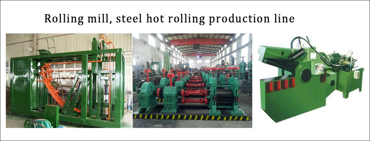
This equipment uses the continuous casting and rolling process to produce electrical aluminum rods, and the rod diameter is ¢ 10mm . The raw materials are aluminum ingots or scrap aluminum wires.
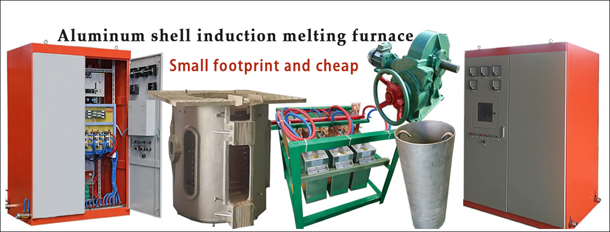
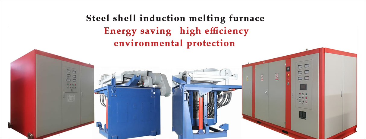
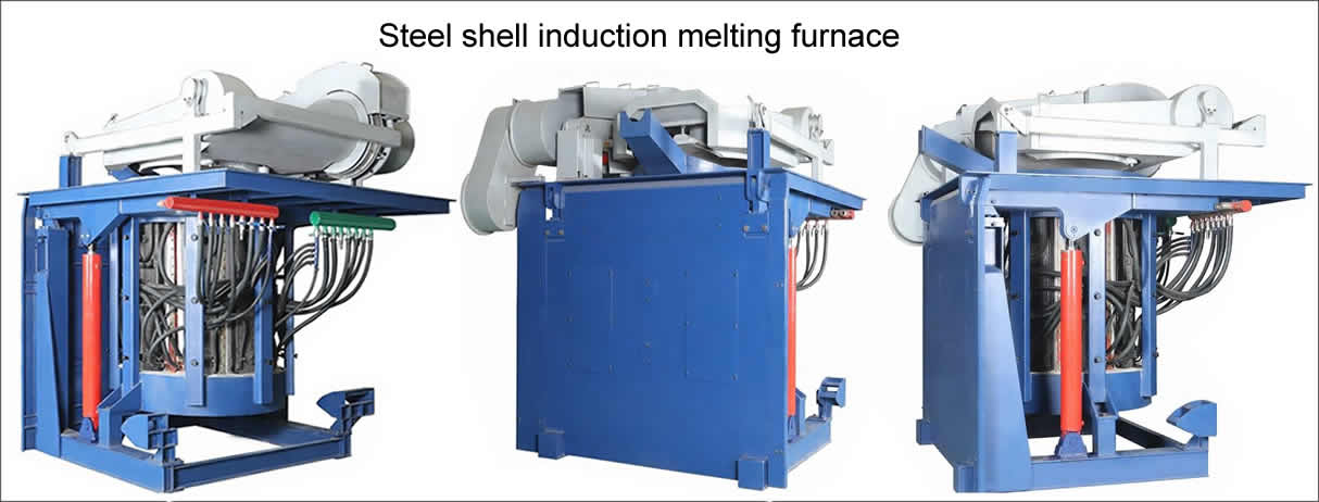
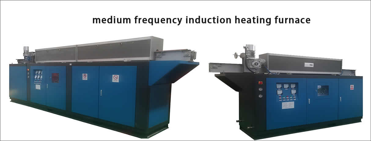
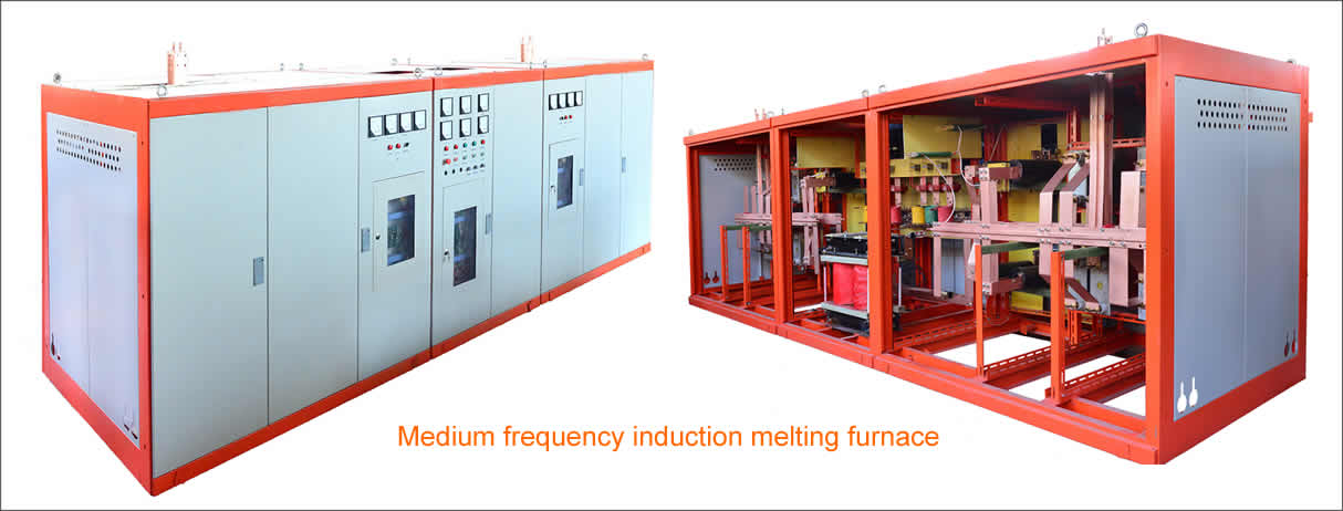
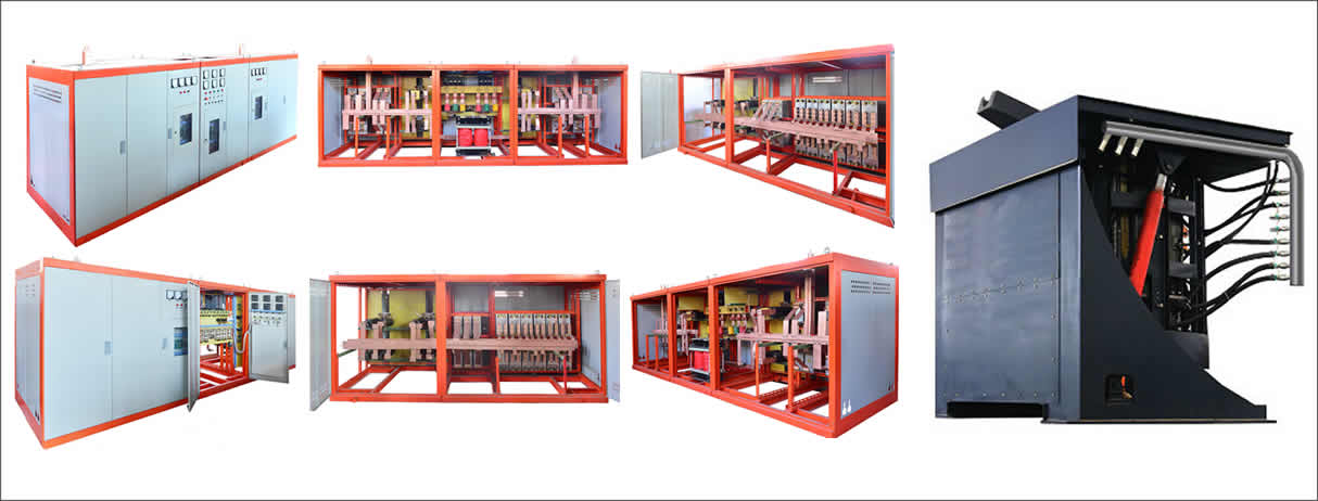
The production line consists of a melting furnace (sharp furnace), a five-wheeled continuous casting machine, an oil shearing machine, a feeding device, a continuous rolling mill, a lubrication system, a cooling system, and a sliding oil-free closing device.
(Which stove is for outsourcing or user-supplied)
specifications
(1) Main technical parameters
Conductive aluminum rod diameter: ¢ 10mm
Production capacity: 2.5-4.8t/h
Total equipment size: 36.05 × 7.2 × 4.2m
Total equipment weight: 55t
(2) Technical parameters of each component:
1 , five-wheel continuous casting machine (four-sided cooling)
1 ), crystal wheel diameter ¢ 1800mm
2 ), the crystal wheel cross-sectional area of 1800mm 2
3) , ingot area 1800mm 2
4 ), casting speed 8-15m / min (motor speed 500-1000rpm )
5 ), crystallization wheel speed 1.66-3.3r/min
6 ), motor model Z4-112/4-2 5.5K 1000r/min
7 ), cooling water pressure 0.35-0.6Mpa
8 ), cooling water volume 100t / h
( internal cooling 40t/h ; external cooling 40t/h ; side cooling 20t/h)
9 ), Poultry lift motor Y901-2 1.1KW 2840r/min
10 ), steel belt compression cylinder 10A-2CDD125B100-Y
11) , steel belt tensioning cylinder 10A-2CDD250B100-Y
2 , oil scissors
3 , continuous rolling mill
1 ), form 2+10 (2 rolls of 2 rolls; 10 sets of three rolls Y type )
2 ), diameter of the rod ¢ 10
3 ), 12 racks
4 ), the nominal size of the roll ¢ 255mm
5 ), adjacent frame transmission ratio 1 : 1.25
6 ), the final rolling speed V = 7.2m / s
7 ), the output is 2.5-4.8t/h
8 ), rolling center height 900mm
9 ), main motor model power Z4-315-22 225kw 680r/min
10 ), gearbox oil tank 3m 3
11 ), emulsion 65m 3
4 , feeding device
Cylinder CA100B75-AB (10A-5)
5 , rolling mill emulsion lubrication system
Lotion pump IS100-65-200 Q=100m 3 /h H=50 15KW 2900r/min
2 sets (one spare)
Filter GLQ-100 1 set with motor 1.1KW
6 , rolling mill oil lubrication system
Gear pump 2CY-18/3.6-1 5.5KW 960r/min 2 sets (one spare)
Working pressure 0.08-0.3Mpa
Filter GLQ-80 with motor 1.1KW 1 set
Fuel tank V = 2m 3 (user site production)
Oil temperature <45 °C
7 , TS - 1800 type looping lower frame
1 ), winding motor type DC12-22
Motor power 1.1kw
Motor speed 1500r/min
2 ), around the head speed of 15-90r / min
3 ), gear reduction motor model JTC-561A
Motor power 2kw
Motor speed 48r/min
4 ), bundled aluminum rod size (unit: mm ) ¢ 1800 × ¢ 800 × 1400 (outer diameter × inner diameter × height)
5 ), bundled aluminum rod weight 2 ~ 2.5t
Third, the unit structure description and characteristics
(1) Five-wheel continuous casting machine
1. Structure: The five-belt belt continuous casting machine consists of a base, a support, a crystal wheel device, a pinch wheel device, a pouring device, an approach bridge, a tensioning wheel device, an external cooling device, a reduction gear box, and a spindle device. Pneumatic control system and other components.
The casting machine adopts an integral structure, and each part is mounted on a unitary base.
2 , the content of the work process
The aluminum liquid flows into the upper gate from the holding furnace, and the flow of the aluminum liquid is controlled by a throttle, and then cast horizontally into the cavity formed by the crystallization crucible and the closed steel strip. Cooling water is sprayed through the nozzle onto the inner surface of the crystallizing wheel, and the aluminum liquid is gradually cooled and solidified into an aluminum ingot at a temperature of 510 ° C to 480 ° C. The solidified aluminum ingot is removed by the starter and finally fed to the continuous rolling mill along the approach bridge.
3 , the structural characteristics of each component
1 ) The crystal wheel device includes a crystal wheel, a pair of plates, a support and a solid piece. The two splints sandwich the crystallizing wheel and are connected by a solid piece. The transmission gearbox is attached to the base, and the crystal wheel device is connected to the clamp plate through the support on the final fixed shaft of the reduction gearbox. The shaft diameter is Φ 140mm , driven by a Z4-112/4-2 DC motor, and the crystal wheel device acts as the main drive wheel. The remaining four steel pulleys act as driven wheels. The casting machine adopts the technology of long steel strip, and the tension of the steel strip is automatically controlled by the pneumatic system.
2 ) The base and the support are welded parts, and the support is fixed on the base and connected by fasteners. A transmission reduction gear box is attached to the base, and the hole is processed together with the driven steel pulley hole.
3 ) The pinch wheel device consists of a Φ 400mm diameter wheel, steering seat, cylinder and connecting piece, and is mounted on the support.
4 ) The tensioning wheel is mounted in the direction of the symmetry of the vertical direction and consists of a cylinder, a rotating arm, a shaft and a direction adjusting mechanism. The device is connected to the hole in the base by a cross pin. By adding a directional adjustment seat, the steel belt is not deflected. The tensioning of the steel strip is performed by the cylinder pulling the arm. The tension of the steel strip is controlled by the cylinder pressure, and the operating speed is also controlled by the flow rate of the exhaust valve.
Each pinch wheel unit has an automatic adjustment. An adjustment mechanism is added to each steel pulley fixing seat; the front end hole of the original fixing seat is changed into a bearing seat, and a self-aligning bearing is added, and the rear end hole is just changed into a four-square box, and four adjusting screws are arranged on the four sides.
The device is specially equipped with a one-way valve in the pressure roller device, the tensioning wheel device and the pneumatic circuit system, and the air pressure can be separately adjusted.
5 ) The ladle device is composed of a ladle, a pouring bracket, a lifting mechanism and a throttling device.
The ladle is welded with a steel plate having a refractory material and a ladle cover with a preheating nozzle. The pouring capacity is about 40 to 80 kg.
The upper part of the casting wheel is provided with an ingot. The starter consists of a bracket and a tin head.
6) The casting machine cooling system is divided into four separate parts, consists of a stainless steel tube bending from, respectively, the cold, cold outside, the inner cold, cold outside. Influent water is controlled by a cooling water distribution tank with a manual flow control valve.
The casting machine adopts an involute approaching bridge as a conveyor belt for the slab, the approach bridge is installed in cooperation with the ingot, and the ingot is used as a tangent to the crystal rim. The approach bridge is supported by a support plate and is equipped with three sets of rollers.
(2) Oil shears
(three) continuous rolling mill
The part of the continuous rolling mill consists of a rolling mill and its oil lubrication system and emulsion lubrication system.
1. The feeding of the rolling mill adopts active feeding, the power is output from the main gear, and the cylinder clamping ingot is boosted and fed into the No. 1 frame.
2 , rolling mill part
The continuous rolling mill consists of 12 subracks. 2 wherein two roll stand; the Y-type three-roll rack 10. The nominal roll diameter is Φ 255 , the even frame is a total of 5 pairs of upper drives , and the odd frame is 5 sets of lower drives . The arc-circle system hole type is adopted. The main drive uses a225kw DC motor to transmit power through the coupling between the coupling and the 12th subrack of the drive case . The gear ratio between the two adjacent subracks is 1 : 1.25 . Each pair of transmission gears has a safety toothed shaft connection at the joint between the front and rear boxes and the frame. Each sub-frame is equipped with an inlet guide before and after, and the odd-numbered rack entrance guide is rolling, and the even-frame entrance guide is sliding. The exit guide mounted at the exit of the frame employs a Hough structure. A stacking automatic parking device is installed between the rack and the rack.
3 , oil lubrication system
The oil in the oil lubricating oil tank passes through the filter through the oil pump, goes to the oil inlet pipe on the rear side of the gear box, enters the gear box in three places, and then sprays the gear through the nozzle of the branch oil pipe; at the same time, the aluminum alloy is respectively connected to the branch oil pipe. The tube is cyclically lubricated by the upper oil hole of each seat, and the oil return is from the lower side of the gear box end through the return pipe to the oil tank.
4 , emulsion lubrication system
The emulsion enters the manifold mounted on the gear box through the centrifugal pump, the filter and the heat exchanger, and the gears, bearings, and inlet and outlet guides of each frame are lubricated through the hose, and finally the emulsion passes through the return tank on the base. The return line is returned to the emulsion tank. The emulsion is also used for the cooling of the slab to remove the extra heat generated by the slab and the rolls during the rolling process, to lubricate and cool the rolls, and to remove the swarf generated during the rolling process.
(4) Sliding oil-free closing device
The unit is mainly composed of sliding wire frame, operating platform, approach bridge, TS-1800 type looping lower wire frame and so on.
1. Approach bridge and operating platform: The approach bridge is a 1/4 arc-shaped ring with rollers on both sides. The two sets of ring rollers form an aluminum rod channel with low friction. Regularly refuel on the wheels.
2 , TS-1800 type looping lower frame
The lower wire frame is a passive wire-receiving type, which is mainly composed of a pipe, a winding mechanism, a collecting bar, and an electric appliance control. The utility model has the advantages of simple structure and convenient operation.
The aluminum rod leaves the frame and enters the conduit. After passing through the grease box, a small amount of grease is applied to the surface of the aluminum rod to reduce friction.
The winding rod is driven by a DC motor, driven by a worm wheel, and the thyristor governor is adjusted.
The closing car is driven by a gear reduction motor and a V-belt, and there are two closing frames on the table.
Five, transmission system diagram and transmission calculation
Drive calculation
1, caster Nnax = 1000 × 25/98 × 25/98 × 19/19 × 19/87 = 2.74r / min
2 , continuous rolling mill
V12max=7.2m/s
The speed ratio between the No. 1 and No. 2 stands is 58/41=1.415
The speed ratio between the 2nd and 3rd frames is 57/42=1.358
The speed ratio between the 3rd and 4th frames is 56/43=1.308
The ratio between the other racks and the rack is 55/44=1.25
Sixth, maintenance and maintenance
(1) Where there is an oil cup or relative movement in the device, the lubricant must be added to the line.
(2) Lubricating station, the emulsion station should always pay attention to the oil level, regularly clean up to prevent blockage, and regularly add new emulsion and lubricating oil to maintain a certain concentration. If it is thicker or discolored, it should be treated in time.
(3) Each transmission gear box must be disassembled and cleaned after 1500 hours of operation, and refilled with new oil or grease.
(4) If the equipment is not used for a long time, the relative moving parts shall be coated with anti-rust grease.
Copyright© 2007-2013 NO.6 Electric Mall All Rights Reserved