Hot search: 3KW electromag
Aluminum forgi
1T one belt tw
15KW electroma

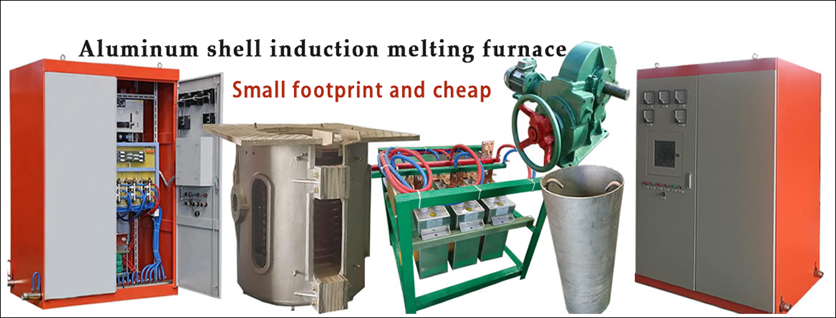
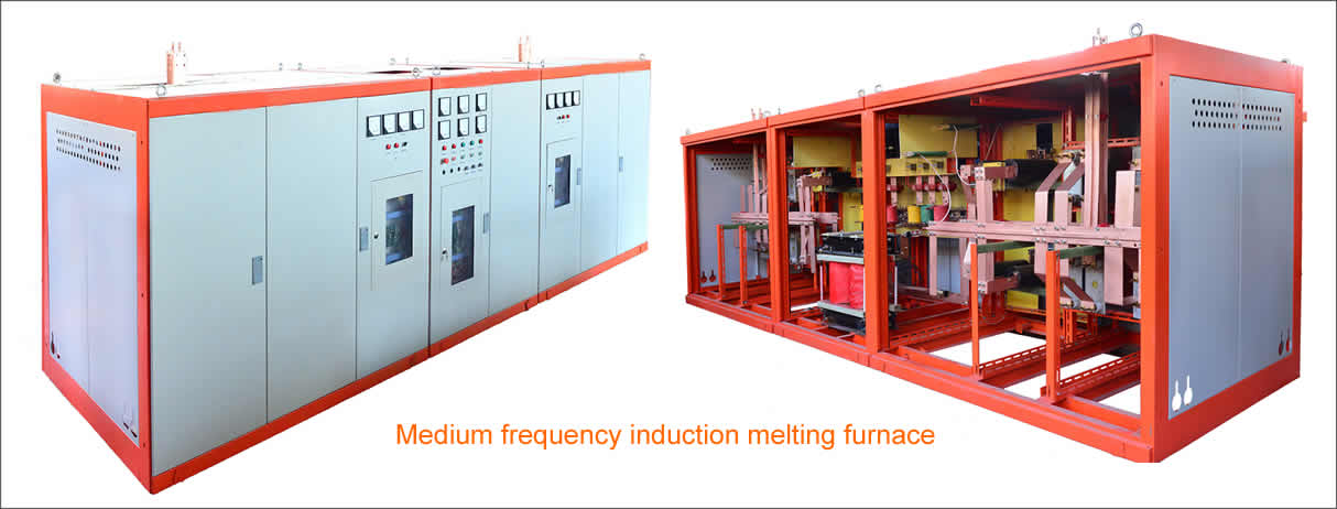
Installation and commissioning of induction melting furnaces and electrical equipment
1. Furnace installation
The installation procedure for the furnace body is specified on the drawings. The first is to install the hob on a flat base, then install the furnace cylinder and furnace body. If there is a weighing device, it should be installed in the specified position according to the drawings. The bracket of the furnace (for the 坩埚-type induction furnace including the fixed bracket and the movable bracket) and the part of the furnace body, during the processing, the amount of thermal deformation caused by the welding construction should be limited within the specified range of the design. Only in this way can the future be ensured. The work went smoothly.
2. Installation and commissioning of water cooling systems
The water cooling system is an important part of the whole furnace installation. The correct installation or commissioning affects the normal operation of the furnace in the future. Before installation and commissioning, first check whether the various pipes, hoses and corresponding joint sizes in the system meet the design requirements. It is best to use galvanized welded pipes for the inlet pipe. If ordinary welded steel pipes are used, the inner wall of the pipe should be pickled before assembly to remove rust and oil. The joints that do not need to be dismantled in the pipeline can be connected by welding method, and the welds are required to be tight, and there should be no leakage during the pressure test. The joint of the detachable part of the pipeline shall be constructed to prevent water leakage and to facilitate maintenance.
The water-cooling system is tested for water pressure resistance after installation. The method is that the water pressure reaches the highest value of the working pressure and is maintained for ten minutes, and all welds and joints are leak-free. Then, the test of water and drainage is carried out to observe whether the flow rates of the cooling water pipes such as the inductor and the water-cooled cable are consistent, and appropriate adjustment is made to meet the requirements.
The backup water source and its switching system should be completed before the first test.
3. Hydraulic system installation and commissioning
The hydraulic drive unit should have the advantages of small size, flexibility and convenience, and convenient operation. Most of the 感应-type induction furnaces adopt hydraulic tilting system. The design of the pumping station should be considered reliable and easy to maintain. There are multiple melting sections of induction furnaces. The hydraulic systems of each furnace should be able to borrow from each other to reduce the time required to stop production due to maintenance of the hydraulic system.
The oil pumping station is generally installed on a base with a certain height, which is convenient for discharging oil from the fuel tank during maintenance, and is conducive to safe production. Even if a serious leak accident occurs, the fuel tank can be protected from the molten iron. When installing the oil pipeline, it is also necessary to start from the worst conditions, and avoid the high temperature and iron phase at any time to prevent the accident from expanding.
Eliminating oil spills in hydraulic systems is a difficult task, starting with improving the quality of the installation. The joints of the oil pipelines that do not need to be disassembled are preferably connected by welding. The weld should be dense and free from leakage. After welding, the inner wall should be cleaned, and no welding slag and scale should be left. The oil pipeline connection with thread connection should be sealed and leakproof in structure. Install appropriate auxiliary measures, such as adding leak-proof coatings, to reduce the possibility of oil leakage during operation.
After the hydraulic system is installed, the test of the entire system should be carried out. The method is to pass 1.5 times the working pressure of the oil for 15 minutes, carefully check the interface of each joint, welding and each component. If there is leakage, measures should be taken to eliminate one by one.
After the furnace body, water cooling system and hydraulic system are installed, the furnace body tilt test should be carried out to check the installation quality of the furnace. If the hydraulic control system is flexible and reliable, whether the actions are correct; whether the furnace body and the furnace cover are operating normally. When the furnace body is tilted to 95°, the limit position switch is insured and adjusts the pressure and flow of the hydraulic system to make it in good working condition. At the same time of tilting the furnace, check the installation quality of the movable joint of the water cooling system, do not leak water and hinder the tilting of the furnace body; check the hose of the hydraulic and water cooling system, observe whether the length is appropriate when the furnace body is tilted, and make appropriate if necessary Adjustment; check whether the drainage system can work normally when the furnace body is tilted. If any defects are found, corresponding measures should be taken.
4. Installation and commissioning of electrical systems and sensors, yokes
The main power supply line of the furnace, transformers, capacitors, reactors, various switchgear and control cabinets, main busbars, power lines and control lines shall be installed in accordance with the relevant regulations of the national industrial enterprise electrical design and installation, pay special attention to The following are the following:
(1) Terminal numbers should be marked on both ends of all control lines between electrical equipment for easy inspection and maintenance. After the wiring is completed, it is necessary to carefully check and test the electrical action so that the operation of all electrical appliances and their interlocks is accurate.
(2) Before the sensor is connected to water, the insulation resistance of the inductor is detected and the withstand voltage test is performed. If the sensor has been vented, the test should be carried out after the water has been blown dry with compressed air. The inductor shall withstand an insulation withstand voltage test of 2Un + 1000 volts (but not less than 2000 volts) for 1 minute without flashover and breakdown. Un is the rated voltage of the sensor. In the high voltage test, the voltage starts from the 1/2Un specified value and increases to the maximum value within 10 seconds.
The insulation resistance between the induction coils and between the induction coils and the ground in the inductor should meet the following requirements: for rated voltages below 1000 volts, with a 1000 volt shaker, the insulation resistance value is not less than 1 megohm; rated voltage is 1000. Above the volt, use a 2500 volt shaker with an insulation resistance value of 1000 ohms. If the insulation resistance value is found to be lower than the above value, the inductor should be dried and dried by means of a heater placed in the furnace or by blowing hot air. However, care should be taken to prevent overheating that is harmful to insulation.
(3) Whether the yoke tightening screw is firm and tight.
Before the furnace is put into operation, it must be confirmed that all the interlocking and signal systems are intact, the tilting position switch is reliable when the furnace body is tilted to the maximum position, and the power supply, measuring instrument and control protection system are in a normal state, and then the furnace is built. Knotted and sintered lining test.
Copyright© 2007-2013 NO.6 Electric Mall All Rights Reserved