Hot search: 3KW electromag
Aluminum forgi
1T one belt tw
15KW electroma

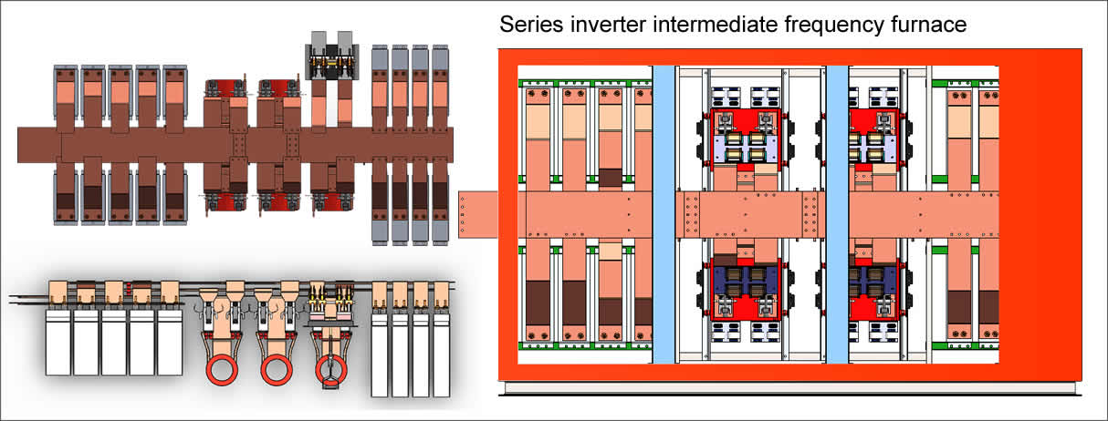
The intermediate frequency power supply is composed of a control circuit, a main circuit, a protection and a sampling circuit.
Control circuit includes: given circuit, PI regulation circuit, PWM PFM circuit, power amplification driver
Circuit. The stepless adjustment of the output power is achieved by controlling the conduction width and frequency of the IGBT.
The main circuit includes: distribution air switch, fuse, rectifier bridge, IGBT, high efficiency IF isolation transformer
It consists of high-efficiency IF compensation capacitors, heat sinks and cooling systems. Input AC power from the power frequency grid through rectification,
LC filtering to obtain smooth DC power, sent to the IGBT inverter, the inverter is the required intermediate frequency AC, and the intermediate frequency
The isolation transformer and the intermediate frequency compensation capacitor are sent to the inductor for heating. Inverter output frequency and conduction width
The degree is controlled by the main control board, and the driving pulse of the main control board is isolated and amplified by the driving board as an IGBT.
Control signal.
Protection and sampling circuit includes: IGBT buffer absorption circuit; temperature monitoring circuit; sensor detection
Road; intermediate frequency voltage, intermediate frequency current, DC voltage and DC current sampling circuit. Overcurrent, overvoltage,
The output can be cut off during overheating to protect the device body and load.
Copyright© 2007-2013 NO.6 Electric Mall All Rights Reserved